
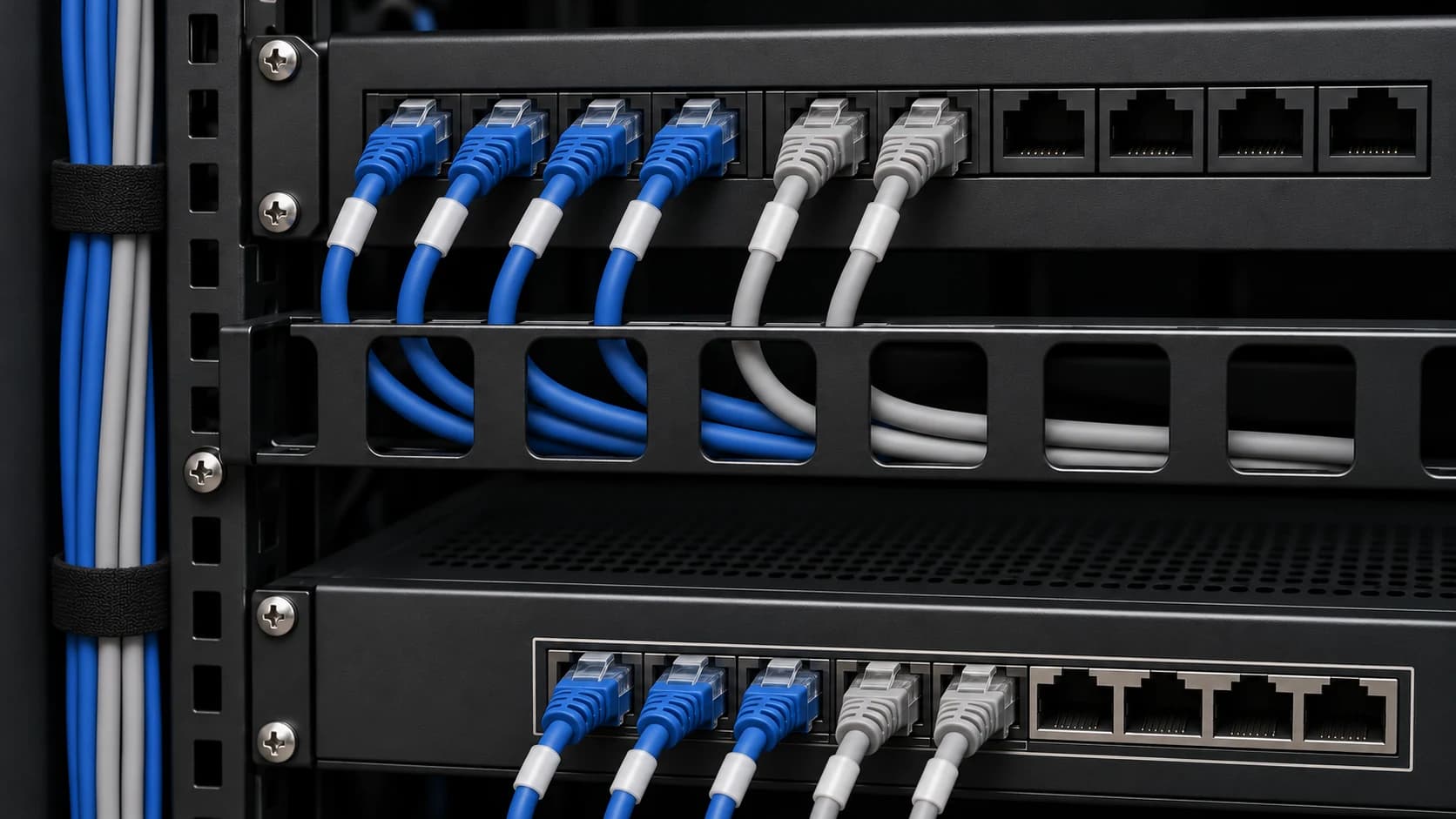
Good cable management protects connections, keeps equipment accessible and helps the next person make a change without interrupting the wrong service. Those benefits matter in a small office cabinet as well as a server room. Begin with the equipment layout and the routes cables must follow. Then choose lead lengths, managers and identifiers that suit those routes. A tidy front view is only useful when the rear connections and records are equally understandable.
Start with a layout that can be maintained
Record rack width, usable height, mounting depth, door clearance, equipment depth and the positions of cable entry points. Mark the direction of airflow for each device rather than assuming every unit uses the same arrangement. Leave access to removable power supplies, fan modules and connectors. Check how a server on sliding rails will move and whether its manufacturer requires a particular cable-management arm.
Place patch panels and switches so leads can reach a defined horizontal route and then the side manager without crossing service areas. Reserve room for rear terminations and supported service length. The illustration is a planning example, not a universal rack design: equipment ventilation and the chosen cabinet's instructions take precedence. Avoid creating a large curtain of cables across a fan inlet or exhaust.
Technical references: Panduit: Horizontal cable manager selection: dimensions and capacity assumptions · IBM: Managing cables: service slack, routing and fibre fastening
Select management by the problem it needs to solve
A manager advertised for a certain cable count is normally based on particular cable dimensions and fill assumptions. A bundle of thick Cat6A installation cables can occupy much more space than the same number of slim patch leads. Read the capacity method and check the narrowest point of the route, including exits, rings and cabinet openings.
Swipe sideways to view all columns
| Requirement | Product type to consider | Confirm before ordering |
|---|---|---|
| Route patching across a panel or switch | Horizontal manager | Rack mounting, height, usable depth, cover clearance and cable capacity |
| Carry leads between rack levels | Vertical manager | Cabinet compatibility, side clearance, entry positions and radius control |
| Hold a bundle that changes regularly | Reusable hook-and-loop fastener | Width, length, environment and a closure that does not compress the cables |
| Identify a lead or termination | Suitable cable/port label | Cable diameter, label format, print compatibility and environmental durability |
| Support cables outside the cabinet | Designed tray, basket or containment | Loading, supports, fill, route conditions and the required installation system |
| Protect fibre routing | Fibre-compatible guides and management | Manufacturer bend-radius limits, protected entry and connector access |
Technical references: Panduit: Horizontal cable manager selection: dimensions and capacity assumptions · Leviton: Cable-management product types for copper and fibre
Measure routes and create a lead-length schedule
Measure along the intended path through managers, not diagonally between sockets. Include the length needed to reach the actual connector, maintain bends and service the equipment. Choose a suitable available lead length, then check that any surplus can be stored without tight coils or pressure on other cables. Never stretch a short lead across the front simply because its labelled length looked sufficient on a drawing.
The following small patching schedule is illustrative. Its service allowances are chosen for the example, not installation rules. Verify real clearances and the available lead lengths before placing an order. A different manager route or moving device can change the calculation.
Swipe sideways to view all columns
| Route group | Measured route + allowance | Example lead choice | Quantity |
|---|---|---|---|
| Nearby panel-to-switch ports | 0.7 m + 0.2 m = 0.9 m | 1 m, if the final route fits | 6 |
| Across the side manager | 1.2 m + 0.2 m = 1.4 m | 1.5 m if available and suitable | 4 |
| Between more distant rack levels | 1.8 m + 0.3 m = 2.1 m | 3 m, with surplus managed safely | 2 |
This example needs 12 leads, but not 12 identical leads. Add category, shielding, connectors and colour to each order line. A smaller-diameter lead may have different channel-length or PoE limits.
Protect bend radius, strain relief and airflow
Use the cable manufacturer's minimum bend radius for the installed condition and, where applicable, the pulling condition. Do not assume the same limit applies to every copper or fibre assembly. Support cable weight so it is not hanging from a connector. Check that closed doors and fitted manager covers do not push a lead into a sharper bend than was visible with the cabinet open.
Reusable hook-and-loop fasteners are useful where bundles need frequent changes. Whatever the fixing, do not tighten it until it deforms the cable. Keep fibre connectors protected and inspect and clean them appropriately before reconnection. A cable can suffer performance loss without obvious damage to its outer jacket.
In an appropriate enclosure layout, blanking panels can reduce air recirculation through unused rack positions. They are not a substitute for checking equipment airflow, heat load or the room's cooling design. Do not block vents merely to make the rack look uniform.
Technical references: IBM: Managing cables: service slack, routing and fibre fastening · Schneider Electric / APC: Rack airflow management and blanking panels
Use separate, traceable pathways
Plan identifiable routes for copper data, fibre and power, with access to each. Separation requirements depend on the cable systems, containment, electrical environment and applicable standards; there is no single spacing figure suitable for every rack and building. Work involving mains distribution, bonding or fire-rated routes needs the appropriate competent design and installation.
Follow the containment manufacturer's load and support instructions and the cable system's fill and thermal requirements. High-power PoE bundles merit particular attention to heating. Keep future additions within the planned capacity rather than forcing one more cable through an already crowded opening. Where a design uses independent power feeds, preserve their intended routing and identification during subsequent changes.
Make labels match a usable port map
Use stable identifiers for infrastructure. A label such as camera can become misleading when the device changes; a rack, panel and port reference remains traceable. Put identifiers at both ends where practical and ensure they can be read without unplugging the connection. Choose labels suited to the cable diameter and environment, and remove obsolete labels when a lead is reassigned.
This example is a local naming scheme, not a claim of compliance with a particular labelling standard. R01 identifies the rack, PP01 the patch panel, SW01 the switch and O01 an outlet. Keep the detailed mapping in one controlled record rather than trying to print every fact on the cable.
Swipe sideways to view all columns
| Permanent-link ID | Outlet | Current patching | Useful record fields |
|---|---|---|---|
| R01-PP01-01 | Room A / O01-A | PP01-01 to SW01-01 | Category, test result, lead length, date |
| R01-PP01-02 | Room A / O01-B | Unpatched spare | Category, test result, reserved purpose |
Use colour only as a secondary cue. Labels and records must still work when a replacement arrives in a different colour or a colleague cannot distinguish the colours reliably.
Make changes in a controlled sequence
After a larger change, retain test or monitoring results where useful and record exceptions that still need attention. The method should remain practical during a busy fault investigation; a presentation-perfect arrangement that cannot be safely serviced is not a successful management system.
- Identify both endpoints, the affected service and its owner. Agree an interruption where necessary before disconnecting anything.
- Record the existing connection and prepare a suitable replacement. Check category, connector, length and any power requirements.
- Route the replacement through the intended managers, keeping bends and service access clear, then connect it at the agreed time.
- Verify the required service and connection performance. Inspect doors, covers and strain relief in their normal closed positions.
- Update the port map and labels, and remove confirmed abandoned patch leads. Do not pull an unidentified cable from a live bundle.
Set a review routine that suits the installation
For a small cabinet, a brief monthly visual review may catch problems early; a larger or critical room needs a suitable inspection and maintenance plan. Look for blocked vents, doors pressing on leads, sagging bundles, lost labels and routes nearing capacity. Check that recent changes appear in the records and that spare ports really are available.
Use findings to prepare a specific purchasing list: manager dimensions, missing supports, appropriate label media and replacement lead lengths. Avoid buying a box of one length and trying to make every route fit it. Photographing the agreed layout can help colleagues understand it, provided sensitive equipment labels and customer information are handled appropriately.
Explore the components covered in this guide
Compare the listed specifications with your equipment and installation requirements before choosing.
Before you buy or send a project enquiry
For a replacement lead or a larger installation, keep these details together so you can compare the listed specifications accurately:
- Cabinet/rack dimensions, mounting requirements, equipment layout and entry points.
- Cable types, diameters, quantities and measured managed routes, including service requirements.
- Required lead lengths, connectors, categories, label formats and compatible product references.
- Environmental, access and delivery constraints; identify any specification still awaiting the installer's confirmation.
Our business and project orders page explains what to include in an enquiry and where to check the current ordering and delivery terms. If a specification is unknown, say so rather than choosing a substitute by appearance.
Sources and further reading
This guide was checked against the following standards and technical resources. Product capabilities can change, so confirm the current manufacturer specification before designing an installation.
This article provides general technical guidance, not a site-specific design. Follow current product instructions and applicable building, electrical and fire requirements; use a competent installer where needed.